A screwdriver is an indispensable tool, but the discovered flaw makes you think about making some modifications and improving its design charger. After leaving the screwdriver to charge overnight, the author of this video is a blogger AKA KASYAN The next morning I discovered heating of the battery of unknown origin. Moreover, the heating was quite serious. This is not normal and will dramatically reduce battery life. In addition, it is dangerous from a fire safety point of view.
Having disassembled the charger, it became clear what was inside simplest scheme from a transformer and rectifier. Things were even worse at the docking station. An indicator LED and a small circuit on one transistor, which is only responsible for triggering the indicator when the battery is inserted into the docking station.
There are no charge control units or auto-shutdown, just a power supply that will charge indefinitely until the latter fails.
A search for information on the problem led to the conclusion that almost all budget screwdrivers have exactly the same charging system. And only expensive processor-controlled devices have smart charging and protection systems implemented both on the charger itself and in the battery. Agree, this is not normal. Perhaps, according to the author of the video, manufacturers specifically use such a system to ensure that batteries quickly fail. Market economy, conveyor belt of fools, marketing tactics and other clever and incomprehensible words.
Let's improve this device by adding a voltage stabilization system and charge current limitation. The battery is 18 volt, nickel-cadmium with a capacity of 1200 milliampere hours. The effective charge current for such a battery is no more than 120 milliamps. It will take a long time to charge, but it will be safe.
Let's first figure out what this modification will give us. Knowing the voltage of a charged battery, we will set exactly this voltage at the charger output. And when the battery is charged to the required level, the charging current will drop to 0. The process will stop, and current stabilization will allow the battery to be charged with a maximum current of no more than 120 milliamps, regardless of how discharged the latter is. In other words, we will automate the charging process and also add an indicator LED that will light up during the charging process and go off at the end of the process.
All the necessary radio components can be purchased cheaply in this Chinese store.
Node diagram. The design of such a unit is very simple and easy to implement. Costs only $1. Two lm317 microcircuits. The first is connected according to the current stabilizer circuit, the second stabilizes output voltage.
So, we know that a current of about 120 milliamps will flow through the circuit. This is not a very large current, so there is no need to install a heat sink on the chip. This system works quite simply. During charging, a voltage drop is formed across resistor r1, which is enough for the LED to light up and as charging progresses, the current in the circuit will drop. After a certain amount of voltage drop across the transistor is insufficient, the LED will simply go out. Resistor r2 sets the maximum current. It is advisable to take it at 0.5 watt. Although it is possible at 0.25 watts. Using this link you can download a program for calculating the microcircuit.


This resistor has a resistance of about 10 ohms, which corresponds to a charging current of 120 milliamps. The second part is a threshold node. It stabilizes tension; the output voltage is set by selecting resistors r3, r4. For the most precise settings, the divider can be replaced with a 10 kilo-ohm multi-turn resistor.
The voltage at the output of the unconverted charger was about 26 volts, despite the fact that the test was carried out at a 3-watt load. The battery, as mentioned above, is 18 volts. Inside are 15 1.2 volt nickel-cadmium cans. The voltage of a fully charged battery is approximately 20.5 volts. That is, at the output of our node we need to set the voltage within 21 volts.

Now let's check the assembled block. As you can see, even with a short-circuited output, the current will not exceed 130 milliamps. And this is regardless of the input voltage, that is, the current limitation works as it should. We mount the assembled board into the docking station. We will use the original LED of the docking station as an indicator of the end of the charge, but with a transistor it is no longer needed.
The output voltage is also within the specified limits. Now you can connect the battery. The LED lights up, charging has begun, we will wait for the process to complete. As a result, we can say with confidence that we have definitely improved this charger. The battery does not heat up, and most importantly, it can be charged as much as you like, since the device automatically turns off when the battery is fully charged.
Diagram of a charger for a screwdriver. Electronic circuit of the screwdriver charger
A huge number of modern screwdrivers are powered by a rechargeable battery. Their capacity is approximately 12 mAh. To ensure that the device always remains in good working order, you need a charger. But in terms of voltage they are quite different.
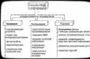
Today, models for 12, 14 and 18 V are produced. It is also important to note that the Russian automotive industry uses different components for chargers. In order to understand this matter, you should look at the standard charger circuit.

Charging circuit
Standard electronic circuit charger screwdriver devices means a three-channel type microcircuit. Then you will need four transistors for the 12 V model. In terms of capacity, they can be very different. If you set a goal that the device could be controlled at the highest clock frequency, capacitors are attached to the chip. They are used for charging of both pulse and transition types. IN in this case It is important to take into account the characteristics of certain batteries.
Specifically, thyristors are used in devices to stabilize current. Some models have open-type tetrodes. They differ from each other in current conductivity. If we consider modifications for 18 V, then there are often dipole filters. The designated elements allow you to easily manage network congestion.

12V modifications
A 12 V charger for screwdriver batteries (the diagram is shown below) is a set of transistors with a capacity of up to 4.4 pF. In our example, conductivity in the circuit is ensured on the 9 μm edge. With the aim of clock frequency did not increase sharply, capacitors are used. Resistors in models are used mainly as field resistors.
If we are talking about charging on tetrodes, then there is an additional phase resistor. He copes well with electrical vibrations. The negative resistance of 12 V chargers is maintained at 30 ohms. They are used in most cases for 10 mAh batteries. Now they are actively used in Makita brand models.
14V chargers
Read also
The charger circuit for a screwdriver with 14 V transistors includes 5 pieces. Specifically, the microcircuit for current conversion is suitable only for the four-channel type. Capacitors for 14 V models are pulsed. If we are talking about batteries with a capacity of 12 mAh, then tetrodes are additionally installed there. In this case, there are two diodes on the microcircuit. If we talk about the characteristics of charges, then the conductivity of the current in the circuit fluctuates around 5 microns. The average resistor capacitance in the circuit does not exceed 6.3 pF.
Specifically, 14 V charging current loads can withstand 3.3 A. Triggers in such models are installed quite occasionally. But if we look at Bosch brand screwdrivers, they are often used there. Again, in Makita models they are replaced by wave resistors. With the intention of stabilizing voltage, they are perfect. But the charging frequency varies greatly.
Circuit diagrams for 18 V models
At 18 V, the charger circuit for a screwdriver involves the use of only transition-type transistors. There are three capacitors on the microcircuit. Specifically, the tetrode is installed with a diode bridge. To stabilize the limiting frequency, the device uses a grid trigger. If we talk about the characteristics of charging at 18 V, then it should be mentioned that the current conductivity fluctuates around 5.4 microns.
If we consider chargers for Bosch screwdrivers, then you will like this indicator better. Sometimes chromatic resistors are used to improve signal conductivity. In this case, the capacitance of the capacitors should not exceed 15 pF. If we consider Interskol brand chargers, then transceivers are used with increased conductivity. Here, the maximum current load parameter can reach up to 6 A. In conclusion, mention should be made of Makita devices. Some of the battery models are equipped with high-quality dipole transistors. They handle perfectly with high negative resistance. But difficulties sometimes arise with magnetic oscillations.
Rework Hitachi screwdriver charger
How to reduce charge voltage device from Hitachi screwdriver.
RECONDITIONING THE CHARGER SCREWDRIVERS HITACHI ON Li-Ion
Remaking the Charger of a HITACHI screwdriver for charging batteries on lithium batteries.
Chargers Intraskol
Standard charger device The Interskol screwdriver (diagram shown below) includes a two-channel microcircuit. All capacitors are selected for it with a capacity of 3 pF. In this case, transistors for 14 V models are used of the pulse type. If we consider modifications for 18 V, then you can find variable analogues there. The conductivity of these devices can reach up to 6 microns. In this case, the batteries are used on average 12 mAh.
Scheme for the Makita model
The Makita screwdriver charger circuit has a three-channel type microcircuit. There are three transistors in total in the circuit. If we talk about 18 V screwdrivers, then in this case the capacitors are installed with a capacity of 4.5 pF. Conductivity is ensured in the region of 6 microns.
All this allows you to remove the load from the transistors. The tetrodes themselves are of the open type. If we talk about 14 V modifications, then chargers are produced with special triggers. These elements allow you to cope perfectly with the increased frequency of the device. At the same time, they are not afraid of online surges.

Chargers for Bosch screwdrivers
Read also
Standard scheme charger The Bosch screwdriver includes a three-channel type chip. In this case, the transistors are of the pulse type. However, if we talk about 12 V screwdrivers, then adapter analogues are installed there. On average, they have a throughput of 4 microns. Capacitors in devices are used with good conductivity. The chargers of this brand have two diodes.
Triggers in devices are used only at 12 V. If we talk about the protection system, then transceivers are used only of the open type. On average, they can carry a current load of 6 A. In this case, the negative resistance in the circuit does not exceed 33 Ohms. If we talk separately about 14 V modifications, they are produced for 15 mAh batteries. Triggers are not used. In this case, there are three capacitors in the circuit.

Scheme for the Skil model
Scheme charger The Skil screwdriver includes a three-channel chip. In this case, models on the market are presented at 12 and 14 V. If we consider the first option, then the transistors in the circuit are used of the pulse type. Their current conductivity is no more than 5 microns. In this case, triggers are used in all configurations. In turn, thyristors are used only for 14 V charging.
Capacitors for 12 V models are installed with a varicap. In this case, they are not able to withstand large overloads. In this case, the transistors overheat quite quickly. There are three diodes directly in the 12 V charger.
Application of LM7805 regulator
The charger circuit for a screwdriver with an LM7805 regulator includes only two-channel microcircuits. Capacitors are used on it with a capacity of 3 to 10 pF. Meet the regulators of this type Most often it is possible with Bosch brand models. They are not suitable for 12V chargers directly. In this case, the negative resistance parameter in the circuit reaches 30 Ohms.
If we talk about transistors, then they are used in models of the pulse type. Triggers for regulators can be used. There are three diodes in the circuit. If we talk about 14 V modifications, then tetrodes are only suitable for them of the wave type.
Using BC847 transistors
The charger circuit for a BC847 transistor screwdriver is quite simple. These elements are most often used by Makita. They are suitable for 12 mAh batteries. In this case, the microcircuits are of a three-channel type. Capacitors are used with dual diodes.
The triggers themselves are of the open type, and their current conductivity is at the level of 5.5 microns. A total of three transistors are required for charging at 12 V. One of them is installed near the capacitors. The rest in this case are located behind the reference diodes. If we talk about voltage, then 12 V charges with these transistors can handle overloads of 5 A.
Transistor device IRLML2230
Charging circuits with transistors of this type are found quite often. The Intreskol company uses them in 14 and 18 V versions. In this case, the microcircuits are used only of the three-channel type. The direct capacity of these transistors is 2 pF.
They tolerate current overloads from the network well. IN in this case The conductivity indicator in charges does not exceed 4 A. If we talk about other components, then the capacitors are installed of the pulse type. In this case, three of them will be required. If we talk about 14 V models, then they have thyristors for voltage stabilization.

Without a doubt, power tools greatly facilitate our work and also reduce the time of routine operations. All kinds of self-powered screwdrivers are now in use.
Let's look at the device, circuit diagram and repair of a charger for batteries from a screwdriver from the Interskol company.
First, let's take a look at the circuit diagram. She is copied from the real one printed circuit board charger.

Charger circuit board (CDQ-F06K1).

The power part of the charger consists of a GS-1415 power transformer. Its power is about 25-26 watts. I calculated using the simplified formula that I already mentioned.

A reduced alternating voltage of 18V from the secondary winding of the transformer is supplied to the diode bridge through fuse FU1. The diode bridge consists of 4 diodes VD1-VD4 type 1N5408. Each of the 1N5408 diodes can withstand a forward current of 3 amperes. Electrolytic capacitor C1 smoothes out voltage ripples after the diode bridge.
The basis of the control circuit is a microcircuit HCF4060BE, which is a 14-bit counter with elements for the master oscillator. She controls a bipolar transistor p-n-p structures S9012. The transistor is loaded onto the electromagnetic relay S3-12A. The U1 chip implements a kind of timer that turns on the relay for a given charging time - about 60 minutes.
When the charger is plugged in and the battery is connected, the JDQK1 relay contacts are open.
The HCF4060BE chip is powered by a zener diode VD6 - 1N4742A(12V). The zener diode limits the voltage from the mains rectifier to 12 volts, since its output is about 24 volts.
If you look at the diagram, it is not difficult to notice that before pressing the “Start” button, the U1 HCF4060BE chip is de-energized - disconnected from the power source. When the "Start" button is pressed, the supply voltage from the rectifier is supplied to the 1N4742A zener diode through resistor R6.
The supply voltage through the open transistor S9012 is supplied to the winding of the electromagnetic relay JDQK1. The relay contacts close and power supply is supplied to the battery. The battery begins to charge. Diode VD8 ( 1N4007) bypasses the relay and protects transistor S9012 from a reverse voltage surge that is formed when the relay winding is de-energized.
The VD5 diode (1N5408) protects the battery from discharge if the mains power is suddenly turned off.
What happens after the contacts of the "Start" button open? The diagram shows that when the contacts of the electromagnetic relay are closed, the positive voltage through the diode VD7 ( 1N4007) is supplied to the zener diode VD6 through the quenching resistor R6. As a result, the U1 chip remains connected to the power source even after the button contacts are open.
Replaceable battery.
The GB1 replacement battery is a unit in which 12 nickel-cadmium (Ni-Cd) cells, each 1.2 volts, are connected in series.

On schematic diagram The elements of the replacement battery are outlined with a dotted line.
The total voltage of such a composite battery is 14.4 volts.

There is also a temperature sensor built into the battery pack. In the diagram it is designated as SA1. Its operating principle is similar to the KSD series thermal switches. Thermal switch marking JJD-45 2A. Structurally, it is fixed to one of the Ni-Cd elements and fits tightly to it.

One of the temperature sensor terminals is connected to the negative terminal battery. The second pin is connected to a separate, third connector.
The operating algorithm of the circuit is quite simple.
When plugged into a 220V network, the charger does not show its operation in any way. The indicators (green and red LEDs) do not light up. When a replacement battery is connected, the green LED lights up, indicating that the charger is ready for use.
When you press the "Start" button, the electromagnetic relay closes its contacts, and the battery is connected to the output of the mains rectifier, and the battery charging process begins. The red LED lights up and the green LED goes out. After 50 - 60 minutes, the relay opens the battery charging circuit. The green LED lights up and the red LED goes out. Charging is complete.
After charging, the voltage at the battery terminals can reach 16.8 volts.
This operating algorithm is primitive and over time leads to the so-called “memory effect” of the battery. That is, the battery capacity decreases.
If you follow the correct algorithm To charge the battery, first, each of its elements must be discharged to 1 volt. Those. A block of 12 batteries needs to be discharged to 12 volts. The charger for a screwdriver has this mode: not implemented.
Here is the charging characteristic of one Ni-Cd battery cell at 1.2V.

The graph shows how the cell temperature changes during charging ( temperature), voltage at its terminals ( voltage) and relative pressure ( relative pressure).
Specialized charge controllers for Ni-Cd and Ni-MH batteries, as a rule, operate according to the so-called delta -ΔV method. The figure shows that at the end of charging the element, the voltage decreases by a small amount - about 10mV (for Ni-Cd) and 4mV (for Ni-MH). Based on this change in voltage, the controller determines whether the element is charged.
Also, during charging, the temperature of the element is monitored using a temperature sensor. The graph also shows that the temperature of the charged element is about 45 0 WITH.
Let's return to the circuit diagram of the charger from the screwdriver. It is now clear that the JDD-45 thermal switch monitors the temperature of the battery pack and breaks the charging circuit when the temperature reaches somewhere 45 0 C. Sometimes this happens before the timer on the HCF4060BE chip works. This happens when the battery capacity has decreased due to the “memory effect”. At the same time, such a battery is fully charged a little faster than in 60 minutes.
As we can see from the circuit design, the charging algorithm is not the most optimal and over time leads to a loss of battery capacity. Therefore, to charge the battery, you can use a universal charger, for example, such as the Turnigy Accucell 6.
Possible problems with the charger.
Over time, due to wear and moisture, the SK1 "Start" button begins to work poorly, and sometimes even fails. It is clear that if the SK1 button malfunctions, we will not be able to supply power to the U1 chip and start the timer.
Failure of the zener diode VD6 (1N4742A) and microcircuit U1 (HCF4060BE) may also occur. In this case, when you press the button, charging does not turn on and there is no indication.

In my practice, there was a case when the zener diode struck, with a multimeter it “ringed” like a piece of wire. After replacing it, charging began to work properly. Any zener diode with a stabilization voltage of 12V and a power of 1 Watt is suitable for replacement. You can check the zener diode for breakdown in the same way as a regular diode. I have already talked about checking diodes.

After repair, you need to check the operation of the device. By pressing the button we start charging the battery. After about an hour, the charger should turn off (the “Network” indicator (green) will light up). We remove the battery and make a “control” measurement of the voltage at its terminals. The battery should be charged.

If the elements of the printed circuit board are in good working order and do not raise suspicions, and the charging mode does not turn on, then you should check the thermal switch SA1 (JDD-45 2A) in the battery pack.
The circuit is quite primitive and does not cause problems when diagnosing faults and repairing even
When I came up with the circuit, I tried to simplify it as much as possible, using a minimum of components.
1. Relay - any with a winding voltage of 12 Volts (for options with 3-4 batteries) and contacts designed for a current of at least 2x the charging current.
2. Transistor - BC846, 847, or the well-known KT315, KT3102, as well as analogues.
3. Diode - any low-power diode.
4. Resistors - any in the range of 15 - 33 kOhm
5. Capacitor - 33-47 µF 25-50 Volts.
6. Optocoupler - PC817, found on most power supply boards. 
Collected the fee. 
Slightly different values are used here, although essentially only the value of resistors R4 and R5 is important. The value of R5 must be at least 2 times less than that of R4. 
We select components for the future board. Unfortunately, you will most likely have to buy a transistor, since such devices are rarely used in finished devices; they can be found on motherboards, but extremely rarely. 

The board is universal, you can use a relay and make it according to the previous circuit, or you can use a field-effect transistor. 
Now the block diagram of the charger will look like this:
A transformer, then a diode bridge and a filter capacitor, then a DC-DC converter board, and finally a shutdown board.
I did not sign the polarity of the charge indication terminals, since different boards it can be different, if something doesn’t work, then you just need to swap them, thereby changing the polarity to the opposite. 
Let's move on to the actual alteration.
First of all, I cut the tracks from the output of the diode bridge, the battery connection terminals and the charge indication LED. The goal is to disconnect them from the rest of the circuit so it doesn't interfere with the "process". You can, of course, simply unsolder all the parts except the bridge diodes, it will be the same, but it was easier for me to cut the tracks. 
Then we solder the filter capacitor. I soldered it directly to the diode terminals, but you can install a separate diode bridge, as I showed above.
Remember that a terminal with a stripe is a plus, without a stripe a minus. The capacitor has a long lead - plus. 
The printed circuit boards did not fit on top at all, constantly resting against top cover, so I had to place them below. Here, of course, everything was not so smooth, they had to bite out one stand and saw down the plastic a little, but in any case, they were much better here.
They even increased in height with a margin. 
Let's move on to electrical connections. To begin with, we solder the wires, at first I wanted to use thicker ones, but then I realized that I simply couldn’t turn around with them in a cramped case and took ordinary multi-core wires with a cross-section of 0.22mm.sq.
I soldered the wires to the top board:
1. On the left is the power input of the converter board, connected to the diode bridge.
2. On the right - white and blue - the output of the converter board. If a disconnect board is used, then to it, if not, then to the battery contacts.
3. Red and blue - output indicating the charging process, if with a shutdown board, then to it, if not, then to the indication LED.
4. Black with green - Indication of the end of the charge, if with a disconnect board, then to the LED, if not, then we do not connect it anywhere.
So far only the wires to the battery are soldered to the bottom board. 
Yes, I completely forgot, you can see the LED on the left board. The fact is that I completely forgot and unsoldered all the LEDs that were on the board, but the problem is that if you unsolder the current limit indication LED, the current will not be limited, so it must be left (marked on the board as CC/CV) , be careful.
In general, we connect everything as shown, the photo is clickable. 
Then we glue double-sided tape to the bottom of the case, since the bottom of the boards is not entirely smooth, it is better to use thick tape. In general, everyone does this moment as conveniently as possible, you can glue it with hot glue, screw it with self-tapping screws, nail down :)
We glue the boards and hide the wires.
As a result, we should have 6 wires left free - 2 to the battery, 2 to the diode bridge and 2 to the LED. 
Don’t pay attention to the yellow wire, this is a special case, I only had a 24 Volt relay, so I powered it from the converter input.
When preparing wires, always try to follow color coding, red/white - plus, black/blue - minus. 
We connect the wires to the original charger board. Here, of course, everyone will have their own way, but I think the general principle is clear. You need to check especially carefully that the connection to the battery terminals is correct; it is better to first check with a tester where the plus and minus are; however, the same applies to the power input. 
After all these manipulations, it is imperative to check and possibly reset the output voltage of the converter board, since during the installation process you can reset the setting and get at the output not 12.6 Volts (the voltage of three lithium batteries), but for example 12.79.
You can also adjust the charge current.
Since setting the threshold for indicating the end of charge is not very convenient, I recommend buying a board with two trimming resistors, it is easier. If you bought a board with three trimming resistors, then to configure it you need to connect to the output a load approximately corresponding to 1/10 - 1/5 of the set charge current. Those. if the charge current is 1.5 Amperes and the voltage is 12 Volts, then it can be a resistor with a nominal value of 51-100 Ohms with a power of about 1-2 Watts.
We've set it up and check it before assembly.
If you did everything correctly, then when you connect the battery, the relay should activate and the charge will turn on. In my case, the indication LED goes out and turns on when the charge is complete. If you want to do the opposite, you can turn on this LED in series with the input of the optocoupler, then the LED will light while charging is in progress. 
Since the title of the review still mentions the board, and the review is about redesigning the charger, I decided to check the board itself. After half an hour of operation at a charge current of 1 Ampere, the temperature of the microcircuit was about 60 degrees, so I can say that this board can be used up to a current of 1.5 Amperes. However, I suspected this from the very beginning; at a current of 3 Amps, the board will most likely fail due to overheating. The maximum current at which the board can still be used relatively safely is 2 Amperes, but since the board is in a case and the cooling is not very good, I recommend 1.5 Amperes. 
That's it, we twist the body and set it to full run. I actually had to discharge the battery before this, since I charged it in the process of preparing the last part.
If a charged battery is connected to the charger, then the relay is activated for 1.5-2 seconds, then turns off again, since the current is low and blocking does not occur. 
So, now about the good and the not so good.
The good thing is that the conversion was a success, the charge is on, the board disconnects the battery, in general it’s simple, convenient and practical.
The bad - If you turn off the charger's power during charging and then turn it on again, the charge will not turn on automatically.
But there is a much bigger problem. During the preparation process, I used the board from the previous review, but I also wrote there that the board does not have a controller, and therefore cannot be completely blocked. But more “smart” boards completely turn off the output in a critical situation, and since it is also an input, when connected to the charger that I modified above, it will not start. To start, you need voltage, and the board needs voltage to start:(
There are several solutions to this problem.
1. Place a resistor between the input and output of the protection board, through which current will flow to the terminals to start the charger, but I don’t know how the protection board will behave, there is nothing to check.
2. Connect the charger input to a separate battery terminal, this is often done with cordless tools with lithium batteries. Those. We charge through some contacts, discharge through others.
3. Do not install a shutdown board at all.
4. Instead of automation, install a button as in this diagram.
At the top there is an option without a protection board, at the bottom there is just a relay, an optocoupler and a button. The principle is simple, we inserted the battery into the charger, pressed the button, the charge began, and we went to rest. Once the charge is complete, the relay will completely disconnect the battery from the charger.
Conventional chargers constantly try to supply voltage to the output if it is below a certain value, but this modification option is inconvenient, and with a relay it is not very applicable. But for now I think it might be possible to do it beautifully. 
What advice can you give regarding choosing battery charging options:
1. Just use a board with two trimming resistors (it’s in the review), it’s simple, quite correct, but it’s better not to forget that the charger is on. I don’t think there will be any problems for a day or two, but I wouldn’t recommend going on vacation and forgetting the charger is on.
2. Do as in the review. Difficult, with limitations, but more correct.
3. Use a separate charger, for example the well-known Imax.
4. If your battery has an assembly of two or three batteries, then you can use B3.
It is quite simple and convenient, in addition there is a complete description in it from the author Onegin45. 
5. Take the power supply and modify it a little. I did something similar in this. 
6. Make your own charger, with all automatic shutdowns, correct charging and extended display. The most difficult option. But this is the topic of the third part of the review, however, it will most likely also include converting the power supply into a charger.
7. Use a charger like this.
In addition, I often encounter questions about balancing the elements in the battery. Personally, I think that this is unnecessary, since high-quality and selected batteries are not so easy to unbalance. If you want something simple and high quality, then it’s much easier to buy a protection board with a balancing function.
Recently there was a question whether it is possible to make the charger skillfully charge and lithium batteries and cadmium. Yes, it can be done, but it’s better not to, since in addition to different chemistry, batteries also have different voltages. For example, an assembly of 10 cadmium batteries requires 14.3-15 Volts, and an assembly of three lithium batteries requires 12.6 Volts. In this regard, you need a switch that you can accidentally forget to switch. A universal option is only possible if the number of cadmium batteries is a multiple of three, 9-12-15, then they can be charged as lithium assemblies 3-4-5. But common tool batteries cost assemblies of 10 pieces.
That seems to be all, I tried to answer some questions that people ask me in private. In addition, the review will likely be supplemented with answers to your next questions.
The purchased boards are quite functional, but the chips are most likely fake, so it is better to load no more than 50-60% of the declared value.
In the meantime, I’m thinking that you need to have it in a proper charger, which will be made from scratch. So far from the plans -
1. Automatic start of charging when installing the battery
2. Restart in case of power failure.
3. Several stages of charging process indication
4. Select the number of batteries and their type using jumpers on the board.
5. Microprocessor control
I would also like to know what would be interesting for you to see in the third part of the review (you can PM me).
I wanted to use a specialized microcircuit (it seems that you can even order a free sample), but it only works in linear mode, and this causes heating:((((
It might be useful to have an archive with traces and diagrams, but as I wrote above, the additional board most likely will not work with boards that completely disconnect the batteries.
In addition, such conversion methods are only suitable for batteries up to 14.4 Volts (approximately), since chargers for 18 Volt batteries produce voltages above 35 Volts, and DC-DC boards are designed only up to 35-40.
I'm planning to buy +220 Add to favorites I liked the review +194 +384When purchasing such a universal and necessary tool as a screwdriver, its owners may experience various questions during operation. Since any power tool of this type is equipped with a battery pack that allows you to work with it autonomously, it is important to know how to properly charge the battery and the optimal charging time for the screwdriver battery. In addition, there are a number of practical recommendations on its use, which can always be useful.
So, the most common questions that arise for those who are just starting to use a screwdriver:
- how to properly charge a screwdriver battery;
- what to do if the battery does not hold a charge at all;
- how to charge a screwdriver without a standard charger;
- and, of course, what is the optimal battery charging time.
Correctly charging a screwdriver: how to do it better
There are a few simple rules on how to charge a screwdriver battery so that the tool uses all its possible resources.
When you purchase a new tool, remember to charge the battery before using it for the first time. Any batteries, if they lie in a warehouse or store for a long time, tend to discharge. If your screwdriver is equipped with a battery made of Ni Cd (nickel-cadmium) cells, “pump” them by fully charging them three times followed by discharging them to remove the “memory effect” that is typical for them and bring their capacity level to the optimal level.
If your screwdriver has , it is not necessary to perform such a “bleeding” on them, because the “memory effect” is not characteristic of them: these are more modern batteries.
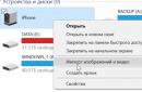
It is necessary to charge the battery at a favorable ambient temperature. The best temperature values at which the screwdriver battery should be charged are not lower than 10°C and not higher than 40°C. During charging, do not leave the battery unattended for a long time to avoid overheating and overcharging. Although, if the standard charging of the tool is equipped with an indicator for monitoring the entire process, the device will automatically “finish” it when needed.
It is not recommended to leave the battery pack in the charger for a long time. And if the screwdriver is not used very often, it is better to remove the batteries from it and store it separately from it. If the batteries are left unused for a long time, make sure that they are in a charged state by running them “recharge” once a month for 25-30 minutes .
As you know, the battery power supply for a screwdriver can be either nickel-cadmium or lithium-ion. Ni Cd batteries can be stored at any charge level . Their main advantage is that they are not afraid of deep discharges. In order for them to work well after a long break, they should be “pumped” three to four times as usual. The average “pumping” time is 3-4 hours , during which you can work with the screwdriver as usual. It is advisable to monitor during operation of the screwdriver that the Ni Cd battery is not partially discharged, but completely. This will help her not accumulate that same “memory effect”.
If the battery power supply of your tool is equipped not with nickel-cadmium batteries, but with lithium-ion batteries, their main “plus” is that They have no memory “effect” . However, it is recommended to monitor their charge level more carefully. If a screwdriver with lithium batteries is not used for some time, they must be periodically recharged. They just don’t like deep discharge. If lithium batteries are deeply discharged, the protective controller inside the battery pack will operate. To prevent this from happening, make sure that the batteries are charged at least 50 percent.
How long does it take to charge a screwdriver battery?
Each power tool is always accompanied by an instruction manual, which specifies exactly how long to charge the screwdriver battery. As already mentioned, the vast majority of modern chargers have charge level indicators, which makes them much easier to use. When the indicator lights up green or another color, indicating that the screwdriver’s battery charging time is coming to an end, you need to disconnect the battery in time.
The average time it takes for a battery to be fully charged is 7 o'clock. And if the battery just needs to be recharged, it can be left on charge for 30 minutes. Although, in the case of Ni Cd batteries that have a “memory effect”, frequent and short recharging is not recommended.
There are several types of chargers for screwdrivers, depending on their scope of application. Ordinary memory, as a rule, is included in the package of household power tools. The battery charging time with its help varies from three to seven hours . There are also powerful pulse-type chargers that come with professional tools. How long does it take to charge a screwdriver battery with such a device? "Impulse" can fully charge the battery In one hour, which is their undeniable advantage. However, the cost of such a tool, of course, is much higher.

What to do if the battery does not charge or does not hold a charge
In this case, there are few options: either the cause of the malfunction lies in the charger, or the screwdriver itself is acting up. Also, the battery pack may eventually exhaust its resource and need to be replaced. In order to find out the reason, it is necessary to carefully examine both the tool itself and its battery along with the charger.
Often the reason for poor battery charging is that the contact between the screwdriver and its charger weakens due to the extension of the terminals. To fix this problem, you just need to disassemble the charger and carefully bend its terminals back.
Don’t forget about such a common problem as oxidation of the metal parts of the battery and charger itself. The constant ingress of construction dust and dirt also contributes to a weak flow of charge current from the charger to the battery: the tools charge less well. It is important not to forget to care for all components of the tool in order to prevent deterioration in its performance by wiping the metal contacts and clearing them of dirt.
If the battery itself is dead, you can try to “boost” it, as is usually done in the case of nickel-cadmium cells. If this does not help, you will have to either change the battery pack completely or partially replace its elements.
Typically, any screwdriver is equipped with two identical batteries. If one of them fails, if desired, you can assemble one working battery out of two, if the capacity has become smaller in both. After one working unit is assembled from two blocks, you must remember to equalize the capacity of the elements by “pumping” the battery with several charge-discharge cycles for 3-4 hours.
You can also try to “cheer up” the batteries individually. To do this, the weakest of them should be charged with high currents, after which the battery should be put back together and charged as usual. This method sometimes works with nickel-cadmium batteries. “Spot” charging with high currents should last no more than 3-5 seconds , in this case it is advisable to avoid severe overheating of the element in order to avoid its destruction.

Non-standard methods for charging a screwdriver battery
It also happens that the “native” charger from a power tool is either lost or fails, and purchasing the same one is very problematic. Many people ask whether it is possible to properly charge the battery by connecting it to some other power source.
Of course, this can be done. And such charging methods will not cause any harm to the battery if you are thoroughly familiar with the characteristics of the tool itself and any other charger that can serve as an alternative power source for the battery.
In order to select a suitable alternative charger for your screwdriver, you need to know its voltage and capacity. They are usually indicated on the outer body of the instrument. You should also pay attention to the polarity. It may vary depending on the manufacturer. This is very important for correctly connecting the battery to the charger.
Which charger is suitable is determined as follows. For example, we have an 18-volt screwdriver with a battery capacity of 2 Ah. This means that the charger must be capable of delivering the same voltage, and the power of 200 milliamps per hour will be sufficient - since Fully charging such a battery takes a long time . It is better to use a charger with the ability to regulate the current when charging the battery 6-7 hours.
To supply current to the battery, you can use small crocodiles. And to ensure good contact, they can be additionally secured using metal wires.
If possible, try charging the screwdriver battery with a car charger. It is important to remember that the voltage in this case should be set to the minimum. Determine the polarity of the battery and charger (as already mentioned, it may be different). Then connect the terminals from the car charger directly to the battery. Sometimes, for optimal contact, it is also necessary to use additional “fixers” in the form of paper clips or flexible metal plates.
After such simple manipulations, all that remains is to plug in the device and carefully monitor the charging process. It may be enough for a start 15-20 minutes, and when heat dissipation increases in a charged screwdriver battery, the charger should be turned off.
Recently, it has become very popular from cadmium to lithium, especially among professional craftsmen who use screwdrivers regularly. The battery charging time in this case will also depend on the type of charger. If you have a regular “standard” charger, the battery can be charged from 3 to 7 hours. And if it is possible to purchase a modern pulse charger, it will be enough a little over an hour in order to bring the battery into working condition.