Before you start working in AutoCAD, it is advisable to configure the program for more convenient and correct use. Most of the default settings in AutoCAD will be enough for a comfortable workflow, but some settings can make drawings much easier.
Today we will talk about AutoCAD settings in more detail.
Setting parameters
Let's start setting up AutoCAD by setting some parameters of the program. Go to the menu, select "Options". On the "Display" tab, select the screen color scheme that is convenient for you.

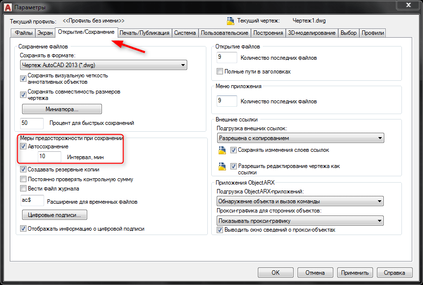
Click the Open/Save tab. Check the checkbox next to the "Autosave" checkbox and set the file saving interval in minutes. It is recommended to lower this number for important projects, but do not increase this number for low-powered computers.
On the Constructions tab, you can adjust the size of the cursor and the autosnap handle. In the same window, you can define the auto-binding parameters. Check the boxes next to "Marker", "Magnet" and "Auto Snap Tooltips".

The size of the crosshair and handles indicating the nodes of the objects are set in the "Selection" tab.
Pay attention to the "Standard box selection" option. It is recommended to check the "Dynamic Lasso Box" checkbox. This will allow you to draw an object selection area with the help of the pressed RMB.

When finished, click "Apply" at the bottom of the settings window.
Don't forget to make the menu bar visible. With it, many frequently used operations will be available.

View customization
Switch to the Viewport Tools panel. Here you can enable or disable the viewcube, navigation bar, and coordinate system icon.
In the adjacent panel (Model Viewports), configure the viewports. Place them as many as you need.
In details:
Open the AutoCAD software. This program is either present as an icon on your desktop, or you can find it in the Start menu in the lower left corner of your screen.
Go to Model Space. There are two types of space in AutoCAD: Model space and Paper space. Your drawing must be made in Model Space, and dimensions added later must be in Paper Space. To switch between model space and paper space, look at the tabs at the bottom of the screen. One tab is called 'Model Space' and the other tabs are called either 'Sheet' or 'Scheme'. The 'Layout' or 'Layout' tabs mean paper space. If currently in Model Space mode, the screen background should be black. If you are in Paper Space mode, the background should be white.
Set the units of measure. Engineers set different units of measure: feet, meters, etc. To ensure accuracy and avoid confusion, it is important that the drawing be made in the correct units. To set the units of measurement, type 'UN' on the keyboard and press the 'ENTER' key. A dialog box should appear that will allow you to specify the units and precision. The type options for units are: Decimal, Scientific, Engineering, Architectural, Fractional. The 'Precision' section will allow you to select the number of decimal places for your dimensions. If you are doing a project for your teacher, he should have information regarding the specification of units of measure.
Select the toolbars that will be used to create your drawing. To do this, move your mouse over the empty space at the top of the screen next to the toolbars. Right click and select "AutoCAD". A long list should appear with various toolbars containing various commands. The most popular toolbars used for 2D drawings in AutoCAD are Draw, Editor, and Object Properties. Select these panels and they should appear on the screen. Move them aside to create space for your drawing. The Draw panel contains the basic drawing tools. The Editor panel contains editing tools. Object Properties panel contains styling and color controls
Turn on Snap mode."Snap", which refers to the binding of objects, is the most important property when creating a drawing. It allows you to see where the midpoint and end point of the line is, the tangent of the circle, and other useful information. To enable Snap mode, press the F3 key on your keyboard. To make sure Snap mode is enabled, right-click on the icon labeled ‘Snap’ in the bottom left corner of the screen. A dialog box should appear on the screen. Click on the ‘Select All’ button, thereby enabling all the binding options.
Having downloaded an archive with a set of line types from our website in the topic "" and now you want to use them, but the question arises: what to do with these files in LIN format, how to add them to AutoCAD? We will tell you about this now.
We take files with linetypes (they consist of three files with the *.LIN *.SHP *.SHX extension) and copy them to the Support folder of the AutoCAD program (or AutoCAD Civil3D, AutoCAD Architecture, AutoCAD Mechanical, etc.) on your computer (for example: C:\Program Files\Autodesk\AutoCAD ****\Support). For convenience, you can create a separate folder, for example Lines.
Then, launch the AutoCAD program and go to the menu Setting to the tab Files.
In the window Access paths, filenames and folders highlight the first line with the name Support File Access Path and press the button Add and then the button Overview. Specify the path to the folder we created earlier lines press OK.
You will see a line indicating the path to the folder Lines. Click on the button Apply and OK.

Now open the window Linetype manager. You can open it in the following ways:

In the window Linetype Manager click on the button Download…

 Specify the path to our line type and open this type in *.LIN format.
Now in the window Available line types select the line you want and press OK.
 Also close the window. Linetype Manager by pressing the OK button.
On the tab Properties click on the drop-down list next to the line type and select our line and
 draw our line with the given type.
The AutoCAD interface is the face of the program, the first thing we see when we open it.
And now, when you finally have AutoCAD installed, let's open it and start getting acquainted with this indispensable assistant in your future adventures.
We will start our acquaintance with the AutoCAD interface.
Versions of the program before 2008 have only a classic look, while in modern versions it is possible to install the AutoCAD interface.
AutoCAD interface. What to choose?
So which interface is better?
Since pattern drawings are usually built along, that is, their height is greater than the width, it is desirable to have the maximum vertical size of the desktop. Therefore, I prefer the classic interface, in which the toolbars are located on the sides, and thus the height of the desktop increases.
To install the classic AutoCAD interface in modern versions, you need to go to the menu Service and in the drop down menu Workspaces select My ClassicAutoCAD.

AutoCAD interface. Main elements of the desktop

1. Menu bar
The traditional drop-down menu bar is located, as in other programs, at the top of the window. It consists of 12 menu groups: File, Edit, View, Insert, Format, Service, Drawing, Dimensions, Edit, Parameterization, Window, Help. Using these menus, you can run commands and determine the state of objects being drawn.
2. Workspace
This is the main part of the screen where all the builds are done.
3. Command line area
Under the workspace is the command line, which consists of two parts: lower and upper.
At the top, important information is given for work.
The lower part is for entering commands from the keyboard. It reflects the actions that the user must perform at this stage of the build. This is a kind of hint for you, where you can see which command is currently being executed and what needs to be done. Therefore, I strongly recommend that you always read the command line until you learn how to work without prompts.
In addition, the command line is used to run any commands, enter coordinates, object parameters, etc. Therefore, its importance in the construction of drawings is difficult to overestimate.
4. Status bar
Below the command line is the status bar. It consists of two parts: left and right. On the left, the cursor coordinates are shown in the Cartesian coordinate system (along the x, y, and z axes). On the right side there are buttons that enable and disable a certain drawing mode.
There are 10 of these modes in total (see the right side of the context menu). But you only need some of them. You can select the ones you need by right-clicking on the status bar. You see the marked 4 modes as 4 buttons in the status bar.

When the button is lit (for example, in the figure, the 2nd button on the left is Object Snap), then the drawing mode corresponding to it is enabled, and if the button is gray, then it is inactive. If you right-click on one of the buttons, a context menu will appear. If you select the "settings ..." item in it, a dialog box for setting this mode will appear. For example, when you click the Object Snap button, you can select snap modes.

5. AutoCAD toolbars
In various areas of the desktop are the so-called toolbars. These are horizontal or vertical panels that include buttons grouped functionally. Each button performs a certain action, or includes lists from which certain items can be selected.
The list of toolbars is quite large, but you don't need much to get the job done.
To select the required panel, you need to right-click on any button of any toolbar and check the box next to the required panel in the expanded list. By ticking a panel in the drop-down list, you find it randomly positioned on the screen. But if the panel is picked up with the mouse by the end, it can be dragged from place to place. In this case, coming close to the edge of the desktop, the toolbar will be located vertically or horizontally, depending on which edge (left, right, top or bottom) it is moved to.
If you uncheck the box next to the panel in the expanded list, then this panel will close, i.e. will become hidden. Also, the toolbar can be closed by dragging it to the middle of the screen and clicking on the cross that appears on the right.
You determine the location of the panels, guided by your desire and ease of use.
As I said earlier, in order to maintain the maximum height of the desktop, my toolbars are located mostly vertically on the left (or right).
The screenshot below shows the panels we need: Object Snap (4), Size (5), Editing (1), Drawing (2), Standard (3), Text (6) - located vertically on the left; Layers (left), Properties (middle), Styles (right) - located at the top, horizontally. On the desktop, these toolbars are already installed in a specific order.

6. Palettes
Entering the menu Service and following in Palettes, you need to choose Properties and QuickCalc(quick calculator). These palettes will be needed for calculations during construction.

When you select a palette from the menu, it appears randomly on the screen. To set the palette on the right side of the screen, Go to it Properties and choose Allow Dock, Dock Right and Automatically hide from the screen. With these properties, the palette will collapse to an icon and be anchored in the upper right corner. When you hover the mouse over the icon, it (the palette) will expand for subsequent actions, and when you move the mouse from the palette field, it will be removed from the screen.


7. Lock Toolbars and Windows
After you have installed in AutoCAD all the tools you personally need for work, I highly recommend blocking their presence and location on the screen. Otherwise, with one wrong mouse click, you may lose or change the interface of your AutoCAD, and you will have to start all the settings from the beginning.

To prevent this from happening, you need to check the "lock" in the right corner of the status bar. It must always be closed. If it is open and Toolbar and Window Positions are unlocked, right-click on the "lock" and select All > Blocked, and all your settings will be saved.

OK it's all over Now. Your AutoCAD is ready to go. Are you ready?
Take a break, and we will begin to get to know your friend and assistant more closely.
See you soon!

AutoCAD program. There are a large number of versions of this program, updates are released almost every year, but it is preferable to keep up with the times and the latest version (preferably Russified), since new features are added to the program, and design becomes more convenient.
Select the project you want to start working on in AutoCAD. Of course, you can take any on the design in this program or use the help in the program menu. But you will learn faster by working on your own project.
When you open the program, as a rule, a window appears, which will be the field of your drawing. By default, the opened file is saved under the name "Drawing1.dwg". Name it after your project. To do this, in the "File" drop-down menu, select the "Save as ..." tab, select the folder where the file and its name will be stored. It is advisable to have a separate AutoCAD folder.
Carefully study the menu of the program. It will not be superfluous to immediately set the types of lines with which the drawing will be drawn. To do this, in the drop-down menu "Format", select the item "Layer ..." and create several layers, specifying the color of the line, its type and thickness. In the future, this will help you not to get confused with dimension and main lines, and when outputting a drawing to a plotter or printer, the lines will be displayed in accordance with their thickness.
Start doing the project. If it’s hard for you to imagine a drawing, try sketching it on paper first, and then gradually transfer it to electronic form. Turn on the bottom toolbar snaps and the function "ORTO". So it will be more convenient for you, because basically the drawings of parts or assembly units are depicted as segments connected at right angles. In the event that it is necessary to draw a segment that will not be perpendicular to any of the coordinate axes, simply turn off "ORTO" by clicking on it with the left mouse button.
Since any drawing consists of line segments, use the main command "Segment" of the drawing panel. To do this, click on the icon with the image of the segment, move the cursor to the drawing area and click the left mouse button. This will be the start of your section. Next, move the cursor in any direction, click the left mouse button again. You marked the end of the segment.
Now try to hover over any point of the resulting segment. The cursor (usually a crosshair in the program) will display anchor icons. With the help of them you can draw perpendicular and parallel segments. At the end point of your segment, an anchor called "Endpoint" will also be displayed, from this point draw a line further, perpendicular to your segment. If you need to cancel the Line command, just press the Esc key.
Try drawing a different type of line (arc or spline) using the drawing panel commands as well. To edit, mirror, lengthen or shorten segments or already finished objects, use the commands of the Editing panel.
Dimension the drawing using the Dimensions menu. Most often, linear dimensions are used, from point to point, drawn parallel to the coordinate axes.
If you have any questions, use the help of the program. In it you will find a user guide that explains the basic concepts of AutoCAD and basic operations, as well as a command reference, since not all program operations can be performed only with a mouse click.
Sources:
- how to work with lines
- AutoCAD 2017 free download autocad Russian version
Mastering any computer program is a process that requires concentration and focus on the task that needs to be solved. This is especially true for computer-aided design systems - programs aimed at solving engineering problems, such as making drawings, drawing up plans, electronic circuits, or creating three-dimensional models of objects.
You will need
- - a computer with AutoCAD installed,
- - Internet connection.
Instruction
Select the project you will be working on in AutoCAD CAD. This may be a drawing of a simple part, such as a bushing or a washer. This way you can quickly learn how to draw in AutoCAD, as you will implement your project, applying, consolidating and practicing the acquired skills in working in the program.
Launch AutoCAD on your computer. The working window of the program will open in front of you. By default, everything you do will be saved in a file called Drawing1.dwg. Try to immediately give the file the desired name, for example "Sleeve.dwg", and save it in the directory from which it will be more convenient for you to work with it. You can do this by opening the "File" tab and selecting "Save As ...".