The standard PT4115 LED driver circuit is shown in the figure below: 
The supply voltage should be at least 1.5-2 volts higher than the total voltage across the LEDs. Accordingly, in the supply voltage range from 6 to 30 volts, from 1 to 7-8 LEDs can be connected to the driver.
The maximum supply voltage of the microcircuit is 45 V, but operation in this mode is not guaranteed (better pay attention to a similar chip).
The current through the LEDs has a triangular shape with a maximum deviation from the average value of ±15%. The average current through the LEDs is set by a resistor and is calculated by the formula:
I LED = 0.1 / R
The minimum allowable value R = 0.082 Ohm, which corresponds to a maximum current of 1.2 A.
The deviation of the current through the LED from the calculated one does not exceed 5%, provided that the resistor R is installed with a maximum deviation from the nominal value of 1%.
So, to turn on the LED for constant brightness, we leave the DIM output hanging in the air (it is pulled up to the 5V level inside the PT4115). In this case, the output current is determined solely by the resistance R.
If a capacitor is connected between the DIM pin and ground, we will get the effect of smooth lighting of the LEDs. The time to reach maximum brightness will depend on the capacitance of the capacitor, the larger it is, the longer the lamp will flare up.
For reference: each nanofarad of capacitance increases turn-on time by 0.8 ms. 
If you want to make a dimmable driver for LEDs with brightness control from 0 to 100%, then you can resort to one of two methods:
- First way involves applying DIM to the input constant voltage in the range from 0 to 6V. In this case, the brightness adjustment from 0 to 100% is carried out at a voltage at the DIM pin from 0.5 to 2.5 volts. Increasing the voltage above 2.5 V (and up to 6 V) does not affect the current through the LEDs (the brightness does not change). On the contrary, a decrease in voltage to a level of 0.3V or lower leads to the shutdown of the circuit and its transfer to standby mode (the current consumption drops to 95 μA). Thus, it is possible to effectively control the operation of the driver without removing the supply voltage.
- Second way implies a signal from a pulse-width converter with an output frequency of 100-20000 Hz, the brightness will be determined by the duty cycle (pulse duty cycle). For example, if high level will keep 1/4 of the period, and the low level, respectively, 3/4, then this will correspond to a brightness level of 25% of the maximum. It must be understood that the frequency of the driver is determined by the inductance of the inductor and in no way depends on the dimming frequency.
The PT4115 LED driver circuit with a constant voltage dimmer is shown in the figure below: 
This LED dimming scheme works great because the DIM pin inside the chip is "pulled up" to the 5V bus through a 200 kΩ resistor. Therefore, when the potentiometer slider is in its lowest position, a voltage divider of 200 + 200 kΩ is formed and a potential of 5/2=2.5V is formed at the DIM pin, which corresponds to 100% brightness.
How the scheme works
At the first moment of time, when the input voltage is applied, the current through R and L is zero and the output key built into the microcircuit is open. The current through the LEDs begins to gradually increase. The rate of current rise depends on the value of the inductance and the supply voltage. The in-circuit comparator compares the potentials before and after the resistor R and, as soon as the difference is 115 mV, a low level appears at its output, which closes the output switch.
Due to the energy stored in the inductance, the current through the LEDs does not disappear instantly, but begins to gradually decrease. The voltage drop across the resistor R also gradually decreases. As soon as it reaches a value of 85 mV, the comparator will again give a signal to open the output key. And the whole cycle repeats from the beginning.
If it is necessary to reduce the current ripple through the LEDs, it is allowed to connect a capacitor in parallel with the LEDs. The larger its capacitance, the more the triangular shape of the current through the LEDs will be smoothed out and the more it will become similar to a sinusoidal one. The capacitor does not affect the operating frequency or efficiency of the driver, but it does increase the settling time for the desired current through the LED. 
Important assembly details
An important element of the circuit is the capacitor C1. It not only smooths out ripples, but also compensates for the energy accumulated in the inductor at the moment the output switch is closed. Without C1, the energy stored in the inductor will flow through the Schottky diode to the power rail and can cause a breakdown of the microcircuit. Therefore, if you turn on the driver without a capacitor shunting the power supply, the microcircuit is almost guaranteed to be covered. And the greater the inductance of the inductor, the more likely it is to burn the mikruha.
The minimum capacitance of the capacitor C1 is 4.7 uF (and when the circuit is powered by a pulsating voltage after the diode bridge, it is at least 100 uF).
The capacitor should be placed as close to the chip as possible and have the lowest possible ESR value (i.e. tantalum conduits are welcome).
It is also very important to responsibly approach the choice of the diode. It should have a low forward voltage drop, a short recovery time during switching, and stable parameters when boosted. temperature p-n transition to prevent an increase in leakage current.
In principle, you can take an ordinary diode, but Schottky diodes are best suited for these requirements. For example, STPS2H100A in SMD version (forward voltage 0.65V, reverse voltage 100V, pulse current up to 75A, working temperature up to 156°C) or FR103 in DO-41 package (reverse voltage up to 200V, current up to 30A, temperature up to 150°C). The common SS34s showed themselves very well, which you can pull from old boards or buy a whole pack for 90 rubles.
The inductance of the inductor depends on the output current (see table below). An incorrectly selected inductance value can lead to an increase in the power dissipated on the microcircuit and beyond the operating temperature range.
When overheated above 160°C, the microcircuit will automatically turn off and remain in the off state until it cools down to 140°C, after which it will start automatically.
Despite the available tabular data, it is allowed to mount a coil with an inductance deviation upwards from the nominal value. This changes the efficiency of the entire circuit, but it remains operational.
The inductor can be taken from the factory, or you can do it yourself from a ferrite ring from a burnt motherboard and PEL-0.35 wires.
If the maximum autonomy of the device is important (portable lamps, lanterns), then, in order to increase the efficiency of the circuit, it makes sense to spend time on careful selection of the throttle. At low currents, the inductance must be larger to minimize current control errors due to the delay in switching the transistor.
The inductor should be located as close as possible to the SW terminal, ideally connected directly to it.
And finally, the most precise element of the LED driver circuit is the resistor R. As already mentioned, its minimum value is 0.082 ohms, which corresponds to a current of 1.2 A.
Unfortunately, it is not always possible to find a resistor of a suitable value, so it's time to recall the formulas for calculating the equivalent resistance when resistors are connected in series and in parallel:
- R last \u003d R 1 + R 2 + ... + R n;
- R pairs = (R 1 xR 2) / (R 1 + R 2).
Combining various ways switching on, you can get the required resistance from several resistors at hand.
It is important to separate the board so that the Schottky diode current does not flow along the track between R and VIN, as this can lead to errors in measuring the load current.
The low cost, high reliability and stability characteristics of the PT4115 driver contribute to its widespread use in LED lamps. Almost every second 12-volt LED lamp with an MR16 base is assembled on a PT4115 (or CL6808). 
The resistance of the current-setting resistor (in ohms) is calculated using exactly the same formula:
R = 0.1 / I LED[A]
A typical wiring diagram looks like this: 
As you can see, everything is very similar to the LED lamp circuit with a PT4515 driver. Description of operation, signal levels, features of the elements used and layout printed circuit board exactly the same as y, so it makes no sense to repeat.
CL6807 is sold at 12 rubles / pc, you just need to watch so that they do not slip soldered ones (I recommend taking it).
SN3350
SN3350 - another inexpensive chip for LED drivers (13 rubles / piece). It is almost a complete analog of PT4115 with the only difference that the supply voltage can range from 6 to 40 volts, and the maximum output current is limited to 750 milliamps (continuous current should not exceed 700 mA).
Like all the above microcircuits, SN3350 is a pulse step-down converter with output current stabilization function. As usual, the current in the load (and in our case, one or more LEDs act as a load) is set by the resistance of the resistor R:
R = 0.1 / I LED
In order not to exceed the value of the maximum output current, the resistance R should not be lower than 0.15 ohm.
The microcircuit is available in two packages: SOT23-5 (maximum 350 mA) and SOT89-5 (700 mA).
As usual, by applying a constant voltage to the ADJ pin, we turn the circuit into a simple adjustable driver for LEDs.
A feature of this microcircuit is a slightly different adjustment range: from 25% (0.3V) to 100% (1.2V). When the potential at the ADJ pin drops to 0.2V, the microcircuit goes into sleep mode with a consumption in the region of 60 μA.
Typical switching circuit: 
For other details, see the chip specification (pdf file).
ZXLD1350
 Despite the fact that this microcircuit is another clone, some differences in technical characteristics do not allow their direct replacement with each other.
Here are the main differences:
- the microcircuit starts already at 4.8V, but it enters normal operation only when the supply voltage is from 7 to 30 Volts (it is allowed to supply up to 40V for half a second);
- maximum load current - 350 mA;
- resistance of the output key in the open state - 1.5 - 2 Ohm;
- By changing the potential at the ADJ pin from 0.3 to 2.5V, you can change the output current (LED brightness) in the range from 25 to 200%. At a voltage of 0.2V for at least 100 µs, the driver goes into sleep mode with low power consumption (about 15-20 µA);
- if the adjustment is carried out by a PWM signal, then at a pulse repetition rate below 500 Hz, the range of brightness change is 1-100%. If the frequency is above 10 kHz, then from 25% to 100%;
The maximum voltage that can be applied to the dimming input (ADJ) is 6V. In this case, in the range from 2.5 to 6V, the driver outputs the maximum current, which is set by the current-limiting resistor. The resistor resistance is calculated in exactly the same way as in all of the above microcircuits:
R = 0.1 / I LED
The minimum resistance of the resistor is 0.27 ohms.
A typical switching circuit is no different from its counterparts: 
It is IMPOSSIBLE to supply power to the circuit without capacitor C1 !!! At best, the chip will overheat and give out unstable characteristics. In the worst case, it will instantly fail.
More detailed specifications ZXLD1350 can be found in the datasheet for this chip.
The cost of the microcircuit is unreasonably high (), despite the fact that the output current is quite small. In general, strongly on the fan. I wouldn't contact.
QX5241
 QX5241 is a Chinese analogue of MAX16819 (MAX16820), but in a more convenient package. Also available under the names KF5241, 5241B. It is marked "5241a" (see photo).
In one well-known store they are sold almost by weight (10 pieces for 90 rubles).
The driver works on exactly the same principle as all of the above (continuous step-down converter), however, it does not contain an output switch, therefore, an external field-effect transistor is required for operation.
You can take any N-channel MOSFET with suitable drain current and drain-to-source voltage. Suitable, for example, are: SQ2310ES (up to 20V !!!), 40N06, IRF7413, IPD090N03L, IRF7201. In general, the lower the opening voltage, the better.
Here are some key features of the QX5241 LED driver:
- maximum output current - 2.5 A;
- Efficiency up to 96%;
- maximum dimming frequency - 5 kHz;
- maximum operating frequency of the converter - 1 MHz;
- current stabilization accuracy through LEDs - 1%;
- supply voltage - 5.5 - 36 Volts (it works fine even at 38!);
- the output current is calculated by the formula: R = 0.2 / I LED
Read more in the specification (in English).
The LED driver on the QX5241 contains few details and is always assembled according to the following scheme: 
The 5241 microcircuit is only available in the SOT23-6 package, so it is better not to approach it with a soldering iron for soldering pans. After installation, the board should be thoroughly washed from the flux, any obscure contamination can adversely affect the operation of the microcircuit.
The difference between the supply voltage and the total voltage drop across the diodes should be 4 volts (or more). If less, then there are some glitches in operation (current instability and throttle whistle). So take it with a margin. Moreover, the greater the output current, the greater the voltage margin. Although, perhaps, I just got an unsuccessful copy of the microcircuit.
If the input voltage is less than the total drop across the LEDs, then the generation fails. At the same time, the output field switch opens completely and the LEDs glow (naturally, not at full power, since the voltage is not enough).
AL9910
 Diodes Incorporated has created one very interesting LED driver IC: the AL9910. It is curious in that its operating voltage range allows you to connect it directly to a 220V network (through a simple diode rectifier).
Here are its main characteristics:
- input voltage - up to 500V (up to 277V for a change);
- built-in voltage regulator for powering the microcircuit, which does not require a quenching resistor;
- the ability to adjust the brightness by changing the potential on the control leg from 0.045 to 0.25V;
- built-in overheating protection (activated at 150°С);
- operating frequency (25-300 kHz) is set by an external resistor;
- an external field-effect transistor is required for operation;
- Available in 8-legged SO-8 and SO-8EP cases.
The driver assembled on the AL9910 chip does not have galvanic isolation from the network, therefore it should be used only where direct contact with the circuit elements is impossible.
must be connected to the mains through special devices that stabilize the current - drivers for LEDs. These are 220 V AC to DC voltage converters with the parameters necessary for the operation of light diodes. Only if they are available, it is possible to guarantee stable operation, long service life of LED sources, declared brightness, protection against short circuits and overheating. The choice of drivers is small, so it's better to first purchase a converter, and then select it for it. You can assemble the device yourself according to a simple scheme. About what a driver for an LED is, which one to buy and how to use it correctly, read our review.
are semiconductor elements. Current, not voltage, is responsible for the brightness of their glow. For them to work, you need a stable current of a certain value. At p-n junction voltage drops by the same number of volts for each element. It is the task of the driver to ensure optimal operation of LED sources, taking into account these parameters.
What kind of power is needed and how much it drops during the p-n junction should be indicated in the passport data of the LED device. The inverter parameter range must fit within these values.

In fact, the driver is. But the main output parameter of this device is a stabilized current. They are produced according to the principle of PWM conversion using special microcircuits or based on transistors. The latter are called simple.
The converter is powered from a conventional network, at the output it produces a voltage of a given range, which is indicated in the form of two numbers: the minimum and maximum values. Usually from 3 V to several tens. For example, using a converter with an output voltage of 9 ÷ 21 V and a power of 780 mA, it is possible to ensure the operation of 3 ÷ 6, each of which creates a 3 V drop in the network.
Thus, the driver is a device that converts the current from the 220 V network to the specified parameters of the lighting device, ensuring its normal operation and long service life.

Where apply
The demand for converters is growing along with the popularity of LEDs. are economical, powerful and compact devices. They are used for a variety of purposes:
- for lanterns;
- at home;
- for arrangement;
- in automobile and bicycle headlights;
- in small lanterns;
When connected to a 220 V network, a driver is always needed; in the case of using a constant voltage, it is permissible to get by with a resistor.

How the device works
The principle of operation of LED drivers for LEDs is to maintain a given output current, regardless of voltage changes. The current passing through the resistances inside the device stabilizes and acquires the desired frequency. Then it passes through a rectifying diode bridge. At the output, we get a stable forward current, sufficient to operate a certain number of LEDs.
Main Features of Drivers
Key parameters of devices for converting current, which you need to rely on when choosing:
- Rated power of the device. It is listed in the range. The maximum value must necessarily be slightly more than the power consumption of the connected lighting device.
- Output voltage. The value must be greater than or equal to the total voltage drop across each circuit element.
- Rated current. It must match the power of the device to provide sufficient brightness.
Depending on these characteristics, it is determined which LED sources can be connected using a specific driver.

Types of current converters by device type
Two types of drivers are produced: linear and pulse. They have one function, but the scope, technical features and cost differ. Comparison of converters different types presented in the table:
| Device type | Specifications | pros | Minuses | Scope of application |
| Current generator on a transistor with a p-channel, smoothly stabilizes the current at an alternating voltage | No interference, inexpensive | Efficiency less than 80%, very hot | Low-power LED lamps, strips, flashlights |
| Works on the basis of pulse-width modulation | High efficiency (up to 95%), suitable for high-power appliances, extends the life of the elements | Generates electromagnetic interference | Car tuning, street lighting, household LED sources |


How to choose a driver for LEDs and calculate its technical parameters
The driver for the LED strip is not suitable for powerful street lamp and vice versa, therefore, it is necessary to calculate the main parameters of the device as accurately as possible and take into account the operating conditions.
| Parameter | What does it depend on | How to calculate |
| Device power calculation | Determined by the power of all connected LEDs | Calculated according to the formula P = source PLED × n , where P is the power of the driver; PLED source – power of one connected element; n - amount of elements. For a power reserve of 30%, you need to multiply P by 1.3. The resulting value is the maximum driver power required to connect the lighting fixture. |
| Output voltage calculation | Determined by the voltage drop across each element | The value depends on the color of the glow of the elements, it is indicated on the device itself or on the packaging. For example, 9 green or 16 red LEDs can be connected to a 12V driver. |
| Current calculation | Depends on the power and brightness of the LEDs | Determined by the parameters of the connected device |
The converters are available with or without housing. The former look more aesthetic and are protected from moisture and dust, the latter are used for flush mounting and are cheaper. Another characteristic that must be taken into account is the permissible operating temperature. For linear and pulse converters it is different.
Important! On the packaging with the device, its main parameters and manufacturer should be indicated.

Ways to connect current converters
LEDs can be connected to the device in two ways: in parallel (several chains with the same number of elements) and in series (one by one in one chain).
To connect 6 elements, the voltage drop of which is 2 V, in parallel in two lines, you need a 6 V 600 mA driver. And when connected in series, the converter must be designed for 12 V and 300 mA.
Serial connection better themes that all LEDs will glow in the same way, while with parallel connection line brightness may vary. When connecting a large number of elements in series, a driver with a large output voltage is required.

Dimmable current converters for LEDs
- This is the regulation of the intensity of light emanating from the lighting device. Dimmable drivers for allow you to change the input and output current parameters. Due to this, the brightness of the LEDs increases or decreases. When using regulation, it is possible to change the color of the glow. If the power is less, then the white elements may turn yellow, if more, then blue.

Chinese drivers: is it worth saving
Drivers are produced in China in huge quantities. They are low cost, so they are quite in demand. They have galvanic isolation. Their technical parameters are often overestimated, so when buying a cheap device, you should take this into account.
Most often these are pulse converters, with a power of 350 ÷ 700 mA. They do not always have a case, which is even convenient if the device is purchased for the purpose of experimentation or training.
Disadvantages of Chinese products:
- simple and cheap microcircuits are used as a basis;
- devices do not have protection against fluctuations in the network and overheating;
- create radio interference;
- create a high-level ripple at the output;
- They don't last long and are not guaranteed.
Not all Chinese drivers are bad, more reliable devices are also being produced, for example, based on PT4115. They can be used to connect household LED sources, flashlights, ribbons.
Driver life
The service life of the LED driver for LED lamps depends on the external conditions and the initial quality of the device. Estimated service life of the driver is from 20 to 100 thousand hours.
The following factors can affect the service life:
- temperature fluctuations;
- high humidity;
- power surges;
- incomplete loading of the device (if the driver is designed for 100 W, but uses 50 W, the voltage returns back, which causes an overload).
Well-known manufacturers give a guarantee for drivers, on average for 30 thousand hours. But if the device has been used incorrectly, then the buyer is responsible. If the LED source does not turn on, or perhaps the problem is in the converter, incorrect connection, or a malfunction of the lighting fixture itself.
How to check the LED driver for performance, see the video below:
Do-it-yourself driver circuit for LEDs with a dimmer based on the PT4115
A simple current converter can be assembled on the basis of a ready-made Chinese PT4115 microcircuit. It is reliable enough to be used. Chip characteristics:
- Efficiency up to 97%;
- there is an output for a device that regulates brightness;
- protected from load breaks;
- maximum stabilization deviation 5%;
- input voltage 6÷30 V;
- output power 1.2 A.
The chip is suitable for powering an LED source over 1W. It has a minimum of strapping components.
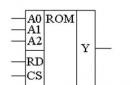
Decoding the outputs of the microcircuit:
- SW– output switch;
- DIM– dimming;
- GND- signal and power element;
- CIN- capacitor
- CSN– current sensor;
- VIN- supply voltage.
Even a novice master can assemble a driver based on this microcircuit.

220V LED lamp driver circuit
The current stabilizer in the case of is installed in the base of the device. And it is based on inexpensive microcircuits, for example, CPC9909. Such lamps must be equipped with a cooling system. They serve much longer than any others, but it is better to give preference to trusted manufacturers, since Chinese ones show manual soldering, asymmetry, lack of thermal paste and other shortcomings that reduce the service life.

How to make a driver for LEDs with your own hands
The device can be made from any unnecessary charger for phone. It is worth making only minimal improvements and the microcircuit can be connected to LEDs. It is enough to power 3 elements of 1 watt. To connect a more powerful source, you can use boards from fluorescent lamps.
Important! During work, safety precautions must be observed. When touching bare parts, an electric shock of up to 400 V is possible.
| A photo | The stage of assembling the driver from the charger |
 | Remove the case from the charger. |
 | Using a soldering iron, remove the resistor that limits the voltage supplied to the phone. |
 | Install a tuning resistor in its place until it needs to be set to 5 kOhm. |
 | Solder the LEDs to the output channel of the device by serial connection. |
 | Remove the input channels with a soldering iron, solder the power cord in their place to connect to a 220 V network. |
 | Check the operation of the circuit, set the regulator to trimmer resistor the right voltage so that the LEDs shine brightly, but do not change color. |
 An example of a driver circuit for LEDs from a 220 V network
 Drivers for LEDs: where to buy and how much they cost
You can buy stabilizers for LED lamps and microcircuits for them in a radio parts store, electrical equipment store and on many online trading platforms. The last option is the most economical. The cost of the device depends on its technical characteristics, type and manufacturer. Average prices for some types of drivers are shown in the table below.
Author's note: “There is a fairly large amount of information on the network about the power supply of LED products, but when I was preparing the material for this article, I found a large amount of absurd information on sites from the top of the issue search engines. At the same time, either a complete absence or an incorrect perception of basic theoretical information and concepts is observed.
LEDs are by far the most efficient of all common light sources. There are also problems behind efficiency, for example, a high requirement for the stability of the current that feeds them, poor tolerance of complex thermal operating conditions (at elevated temperatures). Hence the task of solving these problems. Let's see how the concepts of a power supply and a driver differ. First, let's delve into the theory.
Current source and voltage source
Power Supply is a generic part name electronic device or other electrical equipment that supplies and regulates electricity to power this equipment. It can be located both inside the device and outside, in a separate case.
Driver- the generalized name of a specialized source, switch or power regulator for specific electrical equipment.
There are two main types of power supplies:
Voltage source.
Current source.
Let's look at their differences.
Voltage source- this is such a power supply and the voltage at the output of which does not change when the output current changes.
An ideal voltage source has zero internal resistance, and the output current can be infinitely large. In reality, however, things are different.
Any voltage source has internal resistance. In this regard, the voltage may deviate somewhat from the nominal when a powerful load is connected (powerful - low resistance, high current consumption), and the output current is determined by its internal device.
For a real voltage source, the emergency mode of operation is the short circuit mode. In this mode, the current increases sharply, it is limited only by the internal resistance of the power source. If the power supply does not have short circuit protection, it will fail.
Current source- this is a power source whose current remains set regardless of the resistance of the connected load.
Since the purpose of the current source is to maintain a given level of current. The emergency operating mode for it is the idling mode.
If you explain the reason in simple words, then the situation is as follows: let's say you connected a load with a resistance of 1 ohm to a current source with a nominal 1 ampere load of 1 ohm, then the voltage at its output will be set to 1 volt. A power of 1 watt will be released.
If you increase the load resistance, say, to 10 ohms, then the current will be 1A, and the voltage will already be set at 10V. So, 10W of power will stand out. Conversely, if you reduce the resistance to 0.1 Ohm, the current will still be 1A, and the voltage will become 0.1V.
Idling is the state when nothing is connected to the power supply terminals. Then we can say that at idle the load resistance is very large (infinite). The voltage will rise until a current of 1A flows. In practice, an example of such a situation is the ignition coil of a car.
The voltage on the electrodes of the spark plug, when the power supply circuit of the primary winding of the coil opens, grows until its value reaches the breakdown voltage of the spark gap, after which a current flows through the spark formed and the energy accumulated in the coil is dissipated.

The short circuit condition for the current source is not an emergency operation mode. In the event of a short circuit, the load resistance of the power supply tends to zero, i.e. it is infinitely small. Then the voltage at the output of the current source will be appropriate for the flow of a given current, and the released power is negligible.
Let's move on to practice
If we talk about modern nomenclature or names that are given to power sources to a greater extent by marketers, and not engineers, then power supply is called a voltage source.
These include:
Charging device for mobile phone(in them, the conversion of values \u200b\u200buntil the required charging current and voltage is reached is carried out by converters installed on the board of the device being charged.
Power supply for a laptop.
Power supply for LED strip.
A driver is called a current source. Its main use in everyday life is the power supply of individual and those and others of ordinary high power from 0.5 watts.

LED Power
At the beginning of the article, it was mentioned that the LED has very high power requirements. The fact is that the LED is powered by current. It's connected with . Take a look at her.
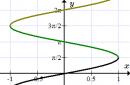
In the picture, the CVC of diodes of different colors:

This branch shape (close to a parabola) is due to the characteristics of semiconductors and impurities that are introduced into them, as well as the features of the pn junction. The current, when the voltage applied to the diode is less than the threshold almost, does not grow, or rather, its growth is negligible. When the voltage at the terminals of the diode reaches the threshold level, the current through the diode begins to increase sharply.
If the current through the resistor grows linearly and depends on its resistance and the applied voltage, then the current growth through the diode does not obey such a law. And with an increase in voltage by 1%, the current can increase by 100% or more.
Plus, for metals, the resistance increases with an increase in its temperature, while for semiconductors, on the contrary, the resistance drops, and the current begins to grow.
To find out the reasons for this in more detail, you need to delve into the course “Physical Foundations of Electronics” and learn about the types of charge carriers, the band gap and other interesting things, but we will not do this, we briefly considered these issues.
In the specifications, the threshold voltage is referred to as the voltage drop in forward bias, for white LEDs is usually about 3 volts.

At first glance, it may seem that at the stage of designing and manufacturing a luminaire, it is enough to fit and expose stable voltage at the output of the power supply and everything will be fine. They do this on LED strips, but they are powered by stabilized power sources, moreover, the power of LEDs used in strips is often* small, tenths and hundredths of watts.

If such an LED is powered by a driver with a stable output current, then when the LED is heated, the current through it will not increase, but will remain unchanged, and the voltage at its terminals will decrease slightly for this.
And if from the power supply (voltage source), after heating, the current will increase, from which the heating will be even stronger.
There is another factor - the characteristics of all LEDs (as well as other elements) are always different.
Driver selection: characteristics, connection
To select the correct driver, you need to familiarize yourself with it. technical specifications, the main ones are:
Rated output current;
Maximum power;
Minimum power. Not always indicated. The fact is, some drivers will not start if a load less than a certain power is connected to them.
Often in stores, instead of power, they indicate:
Rated output current;
Output voltage range as (min.)V…(max.)V, for example 3-15V.
The number of connected LEDs, depends on the voltage range, is written in the form (min) ... (max), for example 1-3 LEDs.
Since the current through all elements is the same when connected in series, therefore, the LEDs are connected to the driver in series.

In parallel, it is undesirable (rather impossible) to connect LEDs to the driver, because the voltage drops on the LEDs may vary slightly and one will be overloaded, and the other, on the contrary, will work in a mode below the nominal one.
Connecting more LEDs than specified by the driver design is not recommended. The fact is that any power source has a certain maximum allowable power that cannot be exceeded. And with each LED connected to a source of stabilized current, the voltage at its outputs will increase by about 3V (if the LED is white), and the power will equal, as usual, the product of current and voltage.
Based on this, we will draw conclusions, in order to buy the right driver for LEDs, you need to decide on the current that the LEDs consume and the voltage that falls on them, and select the driver according to the parameters.

For example, this driver supports connecting up to 12 powerful 1W LEDs, with a current consumption of 0.4A.

This one gives out a current of 1.5A and a voltage of 20 to 39V, which means you can connect to it, for example, an LED for 1.5A, 32-36V and a power of 50W.
Conclusion
A driver is one of the types of power supply designed to provide LEDs with a given current. In principle, it does not matter what this power source is called. Power supplies are called power supplies for LED strips of 12 or 24 Volts, they can produce any current below the maximum. Knowing the correct names, you are unlikely to make a mistake when purchasing a product in stores, and you will not have to change it.
Recently, a friend asked me to help with a problem. He is developing LED lamps, trading them along the way. He has accumulated a number of lamps that are not working properly. Outwardly, this is expressed as follows - when turned on, the lamp flashes for a short time (less than a second), goes out for a second and repeats endlessly. He gave me three such lamps for research, I solved the problem, the malfunction turned out to be very interesting (just like Hercule Poirot) and I want to talk about the troubleshooting path.
The LED lamp looks like this:
Fig 1. Appearance disassembled LED lamp
The developer applied an interesting solution - the heat from the working LEDs is taken by a heat pipe and transferred to a classic aluminum radiator. According to the author, this solution provides the correct thermal conditions for the LEDs, minimizing thermal degradation and ensuring the longest possible life of the diodes. Along the way, the service life of the diode power driver increases, since the driver board is removed from the thermal circuit and the temperature of the board does not exceed 50 degrees Celsius.
Such a decision - to separate the functional zones of light emission, heat removal and supply current generation - made it possible to obtain high performance characteristics of the lamp in terms of reliability, durability and maintainability.
The minus of such lamps, oddly enough, directly follows from its pluses - manufacturers do not need a durable lamp :). Everyone remembers the story of the conspiracy of incandescent lamp manufacturers on a maximum service life of 1000 hours?
Well, I can not help but note the characteristic appearance of the product. My "state control" (wife) did not allow me to put these lamps in a chandelier where they are visible.
Let's get back to driver issues.
This is what the driver board looks like:

Fig 2. External view of the LED driver board from the surface mounting side
And from the reverse side:

Fig 3. External view of the LED driver board from the side of power parts
Studying it under a microscope made it possible to determine the type of control microcircuit - this is MT7930. This is a flyback converter control chip (Fly Back), hung with various protections, like a Christmas tree with toys.
The MT7930 has built-in protections:
From excess current of the key element
lowering the supply voltage
increasing the supply voltage
short circuit in the load and load break.
from exceeding the temperature of the crystal
Declaring protection against a short circuit in the load for a current source is more of a marketing nature :)
It was not possible to obtain a circuit diagram for just such a driver, however, a search on the network turned up several very similar circuits. The closest one is shown in the figure:

Fig 4. LED Driver MT7930. Schematic diagram
An analysis of this circuit and a thoughtful reading of the manual for the microcircuit led me to the conclusion that the source of the flashing problem is the operation of the protection after the start. Those. the initial start-up procedure passes (the flashing of the lamp is what it is), but then the converter turns off due to some of the protections, the power capacitors are discharged and the cycle starts anew.
Attention! There are life-threatening voltages in the circuit! Do not repeat without proper understanding of what you are doing!
To study signals with an oscilloscope, it is necessary to decouple the circuit from the network so that there is no galvanic contact. For this I used an isolating transformer. Two TN36 transformers, still of Soviet production, dated 1975, were found in stocks on the balcony. Well, these are timeless devices, massive, completely covered in green varnish. Connected according to the scheme 220 - 24 - 24 -220. Those. first lowered the voltage to 24 volts (4 secondary windings of 6.3 volts each), and then increased it. The presence of several primary windings with taps gave me the opportunity to play with different supply voltages - from 110 volts to 238 volts. Such a solution is, of course, somewhat redundant, but quite suitable for one-time measurements.

Fig 5. Photo of an isolation transformer
From the description of the start in the manual, it follows that when power is applied, the capacitor C8 begins to charge through resistors R1 and R2 with a total resistance of about 600 kΩ. Two resistors are used out of safety requirements, so that in the event of a breakdown of one, the current through this circuit does not exceed a safe value.
So, the power supply capacitor is slowly charging (this time is about 300-400 ms) and when the voltage on it reaches the level of 18.5 volts, the converter start procedure starts. The microcircuit begins to generate a sequence of pulses to the key field-effect transistor, which leads to the appearance of voltage on the Na winding. This voltage is used in two ways - for the formation of pulses feedback to control the output current (circuit R5 R6 C5) and to form the operating power supply voltage of the microcircuit (circuit D2 R9). At the same time, a current appears in the output circuit, which leads to the ignition of the lamp.
Why does protection work and by what parameter?
First guess
Overvoltage protection operation?
To test this assumption, I unsoldered and checked the resistors in the divider circuit (R5 10k and R6 39k). You can’t check them without soldering, because they are paralleled through the transformer winding. The elements turned out to be serviceable, but at some point the circuit worked!
I checked the waveforms and voltages of the signals at all points of the converter with an oscilloscope and was surprised to see that all of them are completely passport. No deviations from the norm ...
I let the circuit work for an hour - everything is OK.
What if you let it cool down? After 20 minutes in the off state does not work.
Very good, apparently the matter is in the heating of some element?
But what? And what parameters of the element can float away?
At this point, I concluded that there is some kind of temperature-sensitive element on the converter board. Heating this element completely normalizes the operation of the circuit.
What is this element?
Second guess
Suspicion fell on the transformer. The problem was conceived as follows - the transformer, due to manufacturing inaccuracies (say, a winding is unwound for a couple of turns), operates in the saturation region and, due to a sharp drop in inductance and a sharp increase in current, the current protection of the field key is triggered. This is a resistor R4 R8 R19 in the drain circuit, the signal from which is fed to pin 8 (CS, apparently Current Sense) of the microcircuit and is used for the current OS circuit and, if the setting of 2.4 volts is exceeded, turns off the generation to protect the field effect transistor and transformer from damage. On the board under study, there are two resistors R15 R16 in parallel with an equivalent resistance of 2.3 ohms.
But as far as I know, the parameters of the transformer deteriorate when heated, i.e. the behavior of the system should be different - turning it on, working for 5-10 minutes and turning it off. The transformer on the board is very massive and its thermal constant is by no means less than a few minutes.
Maybe, of course, there is a short-circuited coil in it, which disappears when heated?
Soldering the transformer to a guaranteed serviceable one was impossible at that moment (the guaranteed working board had not yet been brought), so I left this option for later, when there are no versions at all :). Plus, the intuitive feeling is not it. I trust my engineering intuition.
At this point, I tested the hypothesis that the current protection was triggered by reducing the OS current resistor by half by soldering the same parallel to it - this did not affect the blinking of the lamp.
This means that everything is fine with the current of the field-effect transistor and there is no current overshoot. This was clearly seen in the waveform on the oscilloscope screen. The peak of the sawtooth signal was 1.8 volts and clearly did not reach the value of 2.4 volts, at which the microcircuit turns off the generation.
The circuit also turned out to be insensitive to a change in load - neither connecting a second head in parallel, nor switching a warm head to a cold one and back did not change anything.
Third assumption
I investigated the supply voltage of the microcircuit. During normal operation, all voltages were absolutely normal. In flashing mode, too, as far as one could judge from the waveforms on the oscilloscope screen.
As before, the system blinked in a cold state and began to work normally when the transformer legs were heated with a soldering iron. Warm up for 15 seconds - and everything starts up normally.
Heating the chip with a soldering iron did nothing.
And the short heating time was very embarrassing ... what can change there in 15 seconds?
At some point, he sat down and methodically, logically cut off everything that was guaranteed to work. If the lamp lights up, then the starting circuits are working.
Once the board is heated, it is possible to start the system and it works for hours, which means that the power systems are working.
Cools down and stops working - something depends on the temperature ...
Crack on the board in the feedback circuit? Cools down and contracts, the contact is broken, heats up, expands and the contact is restored?
I climbed a cold board with a tester - there are no breaks.
What else can interfere with the transition from the start-up mode to the operating mode?!!!
Out of complete hopelessness, I intuitively soldered a 10 microfarad 35 volt electrolytic capacitor in parallel to power the microcircuit.
And then happiness came. Earned!
Replacing the 10 microfarad capacitor with a 22 microfarad one completely solved the problem.
Here it is, the culprit of the problem:

Figure 6. Capacitor with wrong capacitance
Now the mechanism of failure has become clear. The circuit has two microcircuit power circuits. The first, starting one, slowly charges the capacitor C8 when 220 volts are applied through a 600 kΩ resistor. After it is charged, the microcircuit begins to generate pulses for the field worker, starting the power part of the circuit. This leads to the generation of power for the microcircuit in operating mode on a separate winding, which is supplied to the capacitor through a diode with a resistor. The signal from this winding is also used to stabilize the output current.
While the system has not entered the operating mode, the microcircuit is powered by the stored energy in the capacitor. And it was missing a little - literally a couple of percent.
The voltage drop turned out to be enough for the microcircuit protection system to work on reduced power and turn off everything. And the cycle began anew.
It was not possible to catch this supply voltage drop with an oscilloscope - too rough estimate. It seemed to me that everything was fine.
Warming up the board increased the capacitance of the capacitor by the missing percentage - and there was already enough energy for a normal start.
It is clear why only some of the drivers failed with fully functional elements. A bizarre combination of the following factors came into play:
Small capacitance power supply. The tolerance on the capacitance of electrolytic capacitors (-20% + 80%) played a positive role, i.e. capacities with a nominal value of 10 microfarads in 80% of cases have a real capacity of about 18 microfarads. Over time, the capacity decreases due to the drying of the electrolyte.
Positive temperature dependence of the capacitance of electrolytic capacitors on temperature. An increased temperature at the place of output control - literally a couple of degrees is enough and the capacity is enough for a normal start. If we assume that at the place of exit control it was not 20 degrees, but 25-27, then this turned out to be enough for almost 100% passing of the exit control.
Of course, the driver manufacturer saved money by using smaller capacitances compared to the reference design from the manual (22 microfarads are indicated there), but fresh capacitances at elevated temperatures and taking into account the spread of + 80% allowed a batch of drivers to be handed over to the customer. The customer received seemingly working drivers, which eventually began to fail for some unknown reason. It would be interesting to know - did the manufacturer's engineers take into account the behavior of electrolytic capacitors with increasing temperature and the natural spread, or did it happen by accident?
Probably everyone, even a novice radio amateur, knows that in order to connect an ordinary LED to a power source, you need only one resistor. But what if the LED is powerful? Watt so 10. How to be then?
I will show you how to make a simple driver for a powerful LED with just two components.
For the stabilizer-driver we need:
1. Resistor -.
2. Chip - LM317 -.

LM317 is a stabilizer chip. Great for designing regulated power supplies or drivers to power LEDs, as in our case.

Advantages of LM317
- The voltage stabilization range is from 1.7 (including the LED voltage - 3 V) to 37 V. An excellent characteristic for motorists: the brightness will not float at any speed;
- Output current up to 1.5, you can connect several powerful LEDs;
The stabilizer has a built-in protection system against overheating and short circuit. - The negative power supply of the LED in the switching circuit is taken from the power source, therefore, when attached to the car body, the number of mounting wires is reduced, and the body can play the role of a large heat sink for the LED.
High power LED driver circuit

I will connect a 3 watt LED. As a result, we will need to calculate the resistance for our LED. A 1 W LED consumes 350 mA, and a 3 W LED consumes 700 mA (you can see it in the datasheet). Chip LM317 - has a reference voltage of the stabilizer - 1.25 - this is a constant number. It must be divided by the current and get the resistance of the resistor. That is: 1.25 / 0.7 \u003d 1.78 ohms. We take the current in amperes. We choose the nearest resistor by resistance, since there are no resistors with a resistance of 1.78. We take 1.8 and assemble the circuit.
If the power of your LED exceeds 1 W, then the chip must be installed on a radiator. In general, the LM317 is rated for current up to 1.5.
You can power our circuit with a voltage of 3 to 37 volts. Agree, a solid range of nutrition is obtained. But the higher the voltage, the more the microcircuit heats up, keep this in mind.